A guide to installing the Denowatts gateway (v1) and Deno simulators (v3) on a solar array
Inspect Kit Components
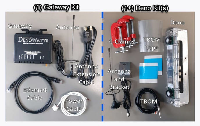
The Denowatts hardware is comprised of (1+) Deno kits and (1) Gateway kit. Some sites additionally may have an Ekor ETPort that is required for installation.
Charge the Denos
The Deno sensors are self-powered from sunlight, so they will not operate fresh out of the box. Before set-up, let's get them charging. There's are two options: 1) Place in direct moderate sunlight for an hour or so; or 2) Charge via USB cable from any power source.
Tip: Some installers charge the units on their dashboard or truck USB while heading to the site.
Don't install the Deno sensors on the solar modules yet
Set up the Gateway
The Gateway will connect your Deno data to the Data Acquisition System (DAS) and will enable remote management. The Gateway must be mounted in a watertight enclosure with the DAS equipment.
- Mount the Gateway to the DIN rail
- Connect the antenna extender cable
- Connect the ethernet cable to the network switch within the DAS enclosure
- Connect to the 12/24Vdc power source within the DAS enclosure
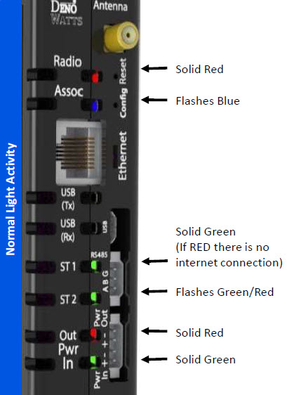
Observe Gateway Lights
Check the lights to confirm the Gateway is properly installed. You should see the following. Pay most attention to "ST1" to confirm that there is a link to the network.
Attach Gateway Antenna
The Gateway antenna must be placed outside the DAS enclosure, as high up as possible. For optimal results, the Gateway antenna should be in the line of sight of the Deno sensor antennas, vertical, if possible.
Deno simulator check with Launch Mode
Before installing the Deno sensors on the solar modules, let's make sure everything is communicating.
- Swipe the antenna underneath the lower pyranometer. As you swipe, you'll see the S-O-L lights momentarily flash. This resets the Deno sensor and shows you that it is powered and ready for action.
- Place and hold the antenna magnet over the upper pyranometer until you see the S-O-L lights illuminate and stay on. The unit is now in Launch Mode.
- Launch Mode overrides normal operation by forcing a 15-second radio transmission under and light condition. This pushes data traffic to the Gateway to confirm communications.
- Check for successful radio communications from the Deno by observing the S-O-L-A-R lights:
- Every 15-seconds the A-R light will flash Red/Green indicating a radio transmission attempt.
- If the transmission is successful the S-O-L lights will all remain ON
- Every time a transmission fails, you will lose an S-O-L light. After three failed transmissions, all S-O-L lights will be OFF, but the radio will keep trying.
Launch Mode uses more power, so it automatically reverts to Normal mode after 10 minutes. To conserve power, reset the Deno with a magnetic swipe under the lower pyranometer once you've confirmed the communications.
If this step fails, please contact Denowatts at 978.496.3460 to diagnose.
Locate the Deno simulators
This is the single-most important installation step for achieving an excellent benchmark.
Re-check Deno Simulator Communication
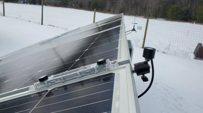
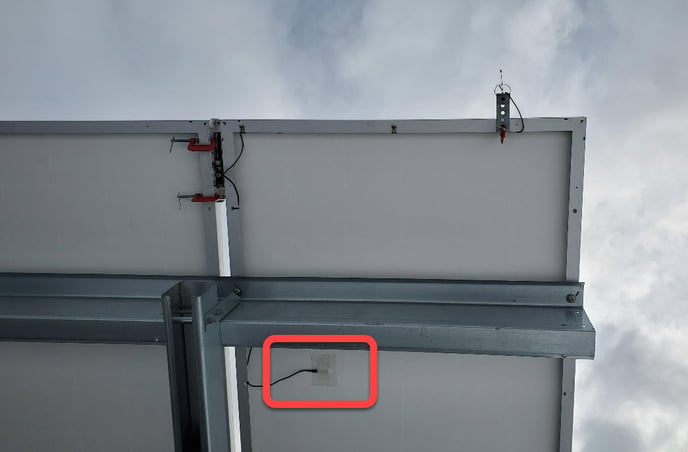
Attach the antenna as far from the Deno sensor as possible to eliminate risk of shading. Once the antenna is mounted, recheck the Deno sensor lights using Launch Mode to ensure the communications are successful. If communications are not succeeding after 2 minutes, move the unit closer to the gateway.
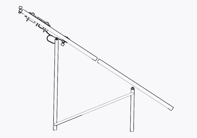
Mount Deno Simulators
The Deno sensor mounts to the side of a solar module frame using (2) c-clamps (included). The sensor MUST be mounted at the top of a solar module or panel in order to properly benchmark.
Prior to attaching, ensure the antenna, Tbom sensor, and (optional) auxiliary pyranometer are all plugged into the back of the Deno.
Single Axis Tracker (SAT) and GHI Den0 Placement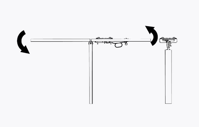
Adhere Back of Module Temperature Sensor
Locate the Back of Module Temperature Sensor (Tbom) approximately 24" adjacent to the Deno sensor. Use the following steps to adhere the sensor with the adhesive tapes (included):
- First clean the Tbom location with a dry cloth
- Apply a layer of Thermal tape and remove blue backing
- Attach the Tbom sensor to the first layer of tape
- Tightly adhere a second layer of thermal tape OVER the Tbom sensor and remove the blue backing. Ensure the tape is wrapped around the sensor as much as possible. This ensures a strong bond and optimal heat transfer.
- Apply the green PET tape over the entire fixture. This ensures protection from the elements of the Tbom.
- Finally, dress up any remaining cable with zip ties or user-provided tape.
Position Auxiliary Pyranometer
The Auxiliary pyranometer may be oriented in the horizontal (GHI) or revere plane of array (rPOA).
If you have a windows PC and USB cable and prefer to utilize the Denowatts Gateway Utility application for this step, please skip this step and click here.
- The serial number of each Deno sensor is reporting at consistent intervals (1-minute daylight, 5-minutes twilight, or 15-minutes night-time)
- The radio signal strength indicator (RSSI) is reading -40 to -60 (excellent), -61--75 (good). If the strength is consistently lower than -76 the signal is weak and you should check the antennas or move the Deno sensor closer to the gateway.
- The Irradiance and temperature sensors are showing accurate measurements.
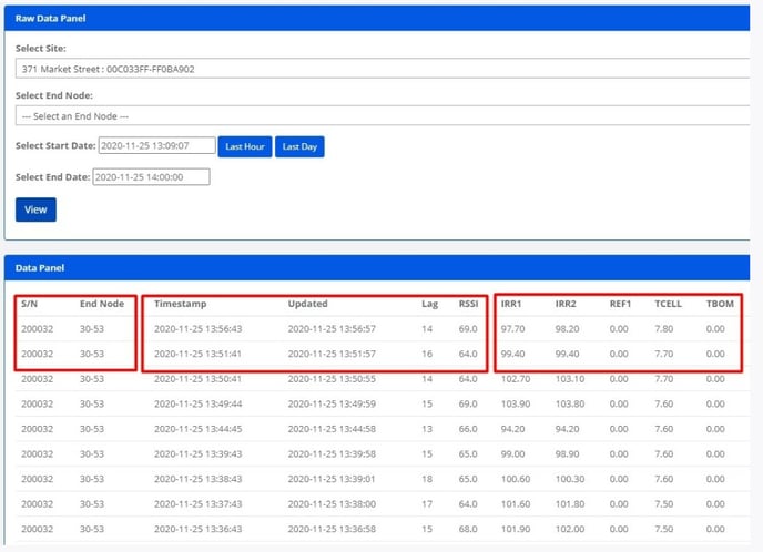
If you do not see data in this screen after 5 minutes and it is reasonably sunny, please contact Denowatts at 978.496.3460.
Document
At this point the Deno hardware installation is complete and we ask you to please take photos of the installed units and mark their location on a site plan, noting Deno serial numbers. These must be uploaded to the Performance Portal for Capacity Test documentation and future reference.
Installation is now complete
Next Step: Sensor Commissioning.